Electrical schematic diagrams are the “blueprints” of electrical systems. They represent circuits using standardized symbols and connections instead of physical appearances. Being able to read them is essential for electricians, engineers, and technicians, because schematics reveal how current flows, how components interact, and where faults may occur. While schematics may look intimidating at first, they can be broken down into logical steps that make them much easier to follow.
1. Understand the Purpose of a Schematic
A schematic does not show the actual physical layout of wires or components. Instead, it illustrates how parts are connected electrically. For example, in a house wiring diagram, switches, outlets, and lamps may not appear in their real-world positions but will be drawn to show how electricity flows between them.
The main purpose is clarity: to simplify complex circuits into readable connections, allowing troubleshooting and design without confusion.
2. Learn Common Electrical Symbols
The foundation of reading schematics is recognising symbols. Every component is represented by a standardised icon, such as:
- Resistor – zig-zag or rectangle
- Capacitor – two parallel lines (with one curved for polarised)
- Diode – a triangle pointing to a line
- Transistor – circle with three terminals (emitter, base, collector)
- Switches – a break in the line with a lever
- Ground – lines converging downward into a point
These symbols are standardised by organisations such as IEC or ANSI. While small regional differences exist, once you learn the basics, you can read nearly any schematic.
3. Follow the Flow of Electricity
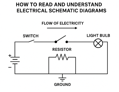
Schematics are often arranged to guide your eye in a logical path. In DC circuits, current typically flows from the positive power supply (at the top or left) through the components, down to the negative or ground (at the bottom or right).
For AC circuits, the arrangement may be left-to-right. Either way, follow the path of current as if it were water flowing through pipes. Identifying entry and exit points of power makes it easier to understand what each component does.
4. Identify Power Sources and References
Most diagrams include a power source symbol (battery, power supply, or AC mains). Ground symbols often appear at multiple points; even though drawn separately, they represent the same electrical connection. Recognising these references helps you avoid confusion when tracing a circuit.
5. Read Connections Carefully
Lines represent wires. Where two lines cross, a dot or node indicates an actual connection. If there’s no dot, the wires simply cross without touching. Misinterpreting this is a common beginner mistake.
In complex schematics, numbers or labels may identify wires instead of long continuous lines. These references allow you to “jump” between parts of the diagram without clutter.
6. Break Down into Subsections
Large circuits can be overwhelming. A helpful method is to divide the schematic into functional blocks, such as:
- Power supply section – where voltage regulation occurs.
- Input section – where signals enter.
- Processing section – where amplification or logic happens.
- Output section – where results (light, motion, sound) are produced.
By analysing one block at a time, you build an understanding of the whole system.
7. Understand Signal Flow and Logic
In digital or control schematics, follow how a switch or sensor triggers an event. For example, pressing a button may close a circuit that energizes a relay coil, which in turn closes another circuit that powers a motor.
This chain of cause and effect is easier to follow if you imagine the circuit “coming alive” step by step.
8. Practice with Simple Diagrams
Start with a basic circuit—like a battery, switch, and lamp. Trace how current flows when the switch is closed. Then move on to slightly more complex diagrams like a relay circuit or a power supply. Each time, ask:
- Where does power enter?
- What path does it take?
- What role does each component serve?
9. Use Reference Materials
Keep a chart of common electrical symbols nearby. Over time, recognition becomes automatic, but at the beginning, a quick reference speeds up learning.
10. Apply Real-World Connections
Finally, tie the schematic to reality. Look at an actual circuit board or wiring harness and try to match what you see with the symbols on paper. This bridge between abstraction and physical hardware is the ultimate skill that makes a schematic useful.
Conclusion
Reading and understanding electrical schematic diagrams is a skill that combines symbol recognition, logical tracing, and functional analysis. By starting with simple circuits, learning the standard symbols, and following current flow methodically, anyone can become proficient. Over time, schematics stop looking like a confusing maze of lines and instead reveal themselves as clear, elegant maps of how electricity does useful work.
Recent Comments